nawergateway.blogg.se

Impulse rc driver fixer searching for flight controller


  1. #IMPULSE RC DRIVER FIXER SEARCHING FOR FLIGHT CONTROLLER SERIAL#
  2. #IMPULSE RC DRIVER FIXER SEARCHING FOR FLIGHT CONTROLLER MANUAL#
  3. #IMPULSE RC DRIVER FIXER SEARCHING FOR FLIGHT CONTROLLER SOFTWARE#
  4. #IMPULSE RC DRIVER FIXER SEARCHING FOR FLIGHT CONTROLLER FREE#

#IMPULSE RC DRIVER FIXER SEARCHING FOR FLIGHT CONTROLLER SOFTWARE#

Few fellow pilots on the channel are doing the incredible job of helping everyone in need, whether it is blackbox log analyzing or troubleshooting hardware and software problems. I have spent a fair amount of time on the channel, collecting info about this release. Judging by the number of channel members, it seems that fair amounts of pilots are already flying this firmware.

#IMPULSE RC DRIVER FIXER SEARCHING FOR FLIGHT CONTROLLER FREE#

If you want to learn more about it and get some help with the installation and tuning, feel free to join the #odin_release slack channel.

impulse rc driver fixer searching for flight controller

“Butterflight_3.5.2_MSD_1.0.0_IMUF_1.0.7-ODIN” is the latest stable release available through the Butterflight configurator. Do not expect to be guided through the installation and setup process, but you can ask for help on the Helio RC Spring Slack workspace and they will be happy to help. It seems that this FC is leaning more towards the more experienced pilots.

#IMPULSE RC DRIVER FIXER SEARCHING FOR FLIGHT CONTROLLER MANUAL#

The board offers a 5V output for powering your external components, although you should be aware that the current limit is up to 2000maĬompared to some other boards like for example the Kakute, there is no provided step-by-step manual for the Helio RC Spring except for the wiring diagram.
impulse rc driver fixer searching for flight controller

  • if you plan to use smart audio, which I’m sure you are, connect it to the tx5 pad on the flight controller.
  • This should give you cleaner video feed in terms of interference. The other way is to power the VTx from the vbat pads on the board and power the camera from the Vtx. You can power the VTx from the battery leads and the camera from the 5v rail on the flight controller.
  • you should connect your FPV camera and VTx (video in and video out) on the third and fifth pad accordingly on the front of the board, the opposite side from the 4in1 ESC port.
  • impulse rc driver fixer searching for flight controller

    This is the pad order from left to right: GND, +5V, SBUS, S-Port.
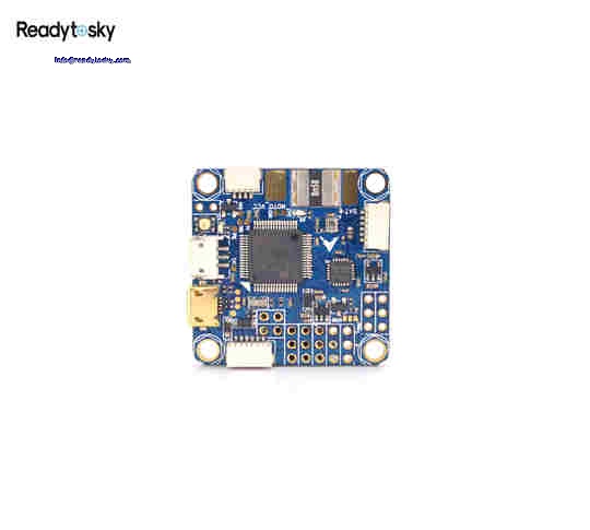
  • the receiver pads are positioned on the top right of the flight controller.
  • Take care that the motor order is correct and use the 5V or vbat lead from the 4in1 if you choose to power your flight controller through the 4in1 cable.
  • connecting the ESCs – when using 4in1 you just need to connect it to the 4in1 ESC port on the Helio RC Spring board.
  • You will have to solder the appropriate bridge connection based on your decision. (photo of the bridged connections, both on top and the ones near the 4in1 connector). In addition, you have an option to use the power lead from your 4in1 ESC or power it directly on the corresponding pads.
  • powering the Helio RC Spring flight controller – depending on your setup you should decide whether you want to power it trough vbat or 5V.
  • The wiring procedure is relatively straightforward and we can divide it into the following steps: Noise issues appear because one inductor on the FC is too close to the ESC. It is worth doing some compatibility research before starting a build based on this flight controller. In some cases when using 4in1 ESCs you may be required to flip the board on the other side or add copper or aluminum tape on the FETs, so you can shield it from ESC electromagnetic interference that may lock up the flight controller mid-flight. To make things easier for you, the front of the board is the opposite side from the one with the 4in1 ESC port. You can refer to the connection diagram for the proper flight controller placement. There is no visual clue about the flight controller orientation. VBAT up to 6s with voltage regulator 2.5A continuous 3.2A burst. Voltage sensing up to 26V, current and RSSI inputs (3.3V max). UART1 and UART2 have inverters for S.Bus and SmartPort telemetry.ĭedicated port for 5V (100mA max) buzzers.

    impulse rc driver fixer searching for flight controller

    #IMPULSE RC DRIVER FIXER SEARCHING FOR FLIGHT CONTROLLER SERIAL#

    Built-in inverter for FrSKY telemetry.ĥ full serial ports (UARTs). PPM, S.Bus (inverter built-in), DSM, HoTT, SRXL, CSRF, FPort ready. 5V or 3.3V supply for receiver.įrSKY Smart Port, FrSKY Sensor Hub, HoTT Telemetry, SRXL, CSRF, FPort ready. Also, there are separate bridges available after the 4in1 connector that enable you to select the proper 4in1 voltage output and current sensor, for powering the board through the 4in1 ESC. The bridges on the board are a very neat feature that enables you to choose how you want to power the board. There are several bridged connections on the Helio RC Spring flight controller. The Helio RC team has taken care to mark everything properly on the new Helio RC Spring AIO board intended for pilots that prefer four separate ESCs. For the ones that are not marked, you will have to look at the connection diagram. There are visible markings on almost all pads.


    Impulse rc driver fixer searching for flight controller